Viewing and Graphics
Viewing
A viewing object manages viewing coordinate system whose origin is located at the position of a virtual camera, -z axis is oriented to the objects observed, and xy-plane is the projection screen. Since viewing inherits class cascaded-coords, it accepts coordinates transformation message such as :translate, :rotate and :transform. Also, it can be attached to another object derived from cascaded-coords, allowing the simulation of the camera-on-mobile-object system. The main purpose of viewing is to transform vectors represented in the world to the camera coordinates system. The transformation is taken in the opposite direction against usual coordinate transformation where vectors in the local coordinates are transformed into the representation in the world. Therefore, viewing holds the inversed left-handed transformation in the viewcoords slot, which is usually referred as the viewing coordinate system.
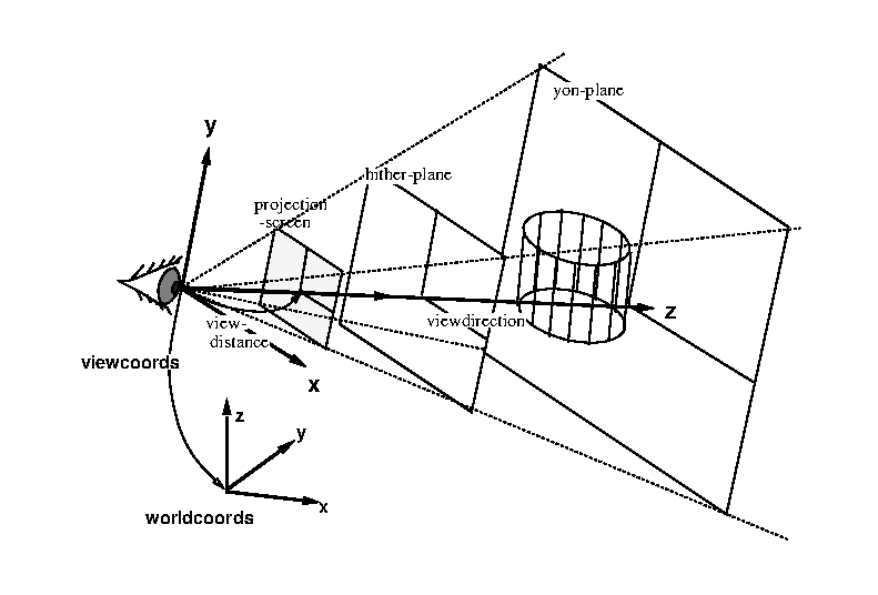
viewing coords and projection planes
viewing
defines the viewing transformation.
:viewpoint **
returns the position vector of the origin of this viewing.
:view-direction **
returns the vector from the origin of the viewing to the center of screen. This is the z-axis direction of the viewing coordinates.
:view-up **
returns y-axis vector of this viewing represented in the world coords. Y-axis is the upward direction in the viewport.
:view-right **
returns x-axis vector of this viewing represented in the world coords. X-axis is in horizontal direction to the right in the viewport.
:look from &optional (to #f(0 0 0))
conveniently sets the viewing coords as the eye is located at from and looking at to point.
Since viewing inherits cascaded-coords, all the :init parameters such as :pos, :rot, :Euler, :rpy, etc. can be used to specify the location and the orientation of the viewing coordinates. However, viewing’s :init provides easier way to determine the rotation. If only :target is given, view-line (-z axis) is determined to pass the viewpoint and :target point, and the :view-right vector is determined so that the x-axis is parallel to the xy-plane of the world coordinates. You may specify :view-direction instead of :target to get the same effect. If you give :view-up or :view-right parameter in addition to :target or :view-direction, you can determine all the three rotation parameters by yourself.
Projection
Class parallel-projection and perspective-projection process projection transformation, which is represented with a 4X4 matrix, i.e., the transformation is taken in the three dimensional homogeneous coordinates. Class projection is an abstract class for both of these. Since these projection classes inherit the viewing class, two coordinates transformation, world-to-viewing and projection can be performed at the same time. By sending the :project3 message with a 3D vector to a projection object, a float-vector of four elements is returned. Homo2normal function is used to convert this homogeneous vector to the normal representation. The result is a vector represented in so called normalized device coordinates (NDC), in which a visible vector ranges within -1 to 1 in each of x,y, and z dimensions. For the simulation of real cameras in a robot world, the perspective projection is used more often than the parallel-projection. Perspective-projection defines a few more parameters. Screenx and screeny are the sizes of the window on the viewing plane on which observed objects are projected, and with the larger screen, the wider space is projected. Viewdistance which defines the distance between the viewpoint and the viewplane also concerns with the viewing angle. The larger viewdistance maps the smaller region to the window on the view plane. Hither and yon parameters determine the distance to the front and back depth clipping planes. Objects outside these two planes are clipped out. Actually, this clipping procedure is performed by the viewport object.
projection
defines projection transformation with a 4x4 matrix.
:projection &optional pmat
if pmat is given, it is set to the projection-matrix slot. :projection returns the current 4x4 projection matrix.
:project vec
is a three-dimensional homogeneous float-vector of four elements. Vec is transformed by projection-matrix, and the resulted homogeneous representation is returned.
:project3 vec
is a normal 3D float-vector. Vec is homogenized and transformed by projection-matrix, and the resulted homogeneous representation is returned.
:view vec
applies viewing transformation and projection transformation to vec successively. The resulted homogeneous representation is returned.
:screen xsize (&optional (ysize xsize))
changes the size of the viewing screen. The larger the size, the wider view you get.
:hither depth-to-front-clip-plane
determines the distance from the viewpoint to the front-clipping plane. Objects before the front-clipping (hither) plane are clipped out.
:yon depth-to-back-clip-plane
changes the distance between the viewpoint and the back-clipping plane. Objects behind the back-clipping (yon) plane are clipped out.
:aspect &optional ratio
Aspect ratio is the ratio between screen-y and screen-x. If ratio is given, the aspect ratio is changed by setting screen-y to screen-x * ratio. :aspect returns the current aspect ratio.
initializes viewing and projection.
parallel-viewing
defines parallel projection. Hid (the hidden-line elimination function) cannot handle parallel projection.
:make-projection **
perspective-viewing
defines a perspective projection transformation.
:make-projection **
:ray u v
returns the normalized direction-vector pointing (u,v) on the normalized screen from the viewpoint.
:viewdistance &optional vd
Viewdistance is the distance between viewpoint and the screen. If vd is given, it is set to viewdistance. The viewdistance corresponds to the focal length of a camera. The greater the viewdistance, the more zoomed-up view you get. :viewdistance returns the current viewdistance.
:view-angle &optional ang
set screen size so that the prospective angle of the diagonal of the screen becomes ang radian. Note that angles somewhat between 20 degree (approx. 0.4 rad.) and 50 degree (0.9 rad.) can generate a natural perspective view. Wider angle generates a skewed view, and narrower a flat view like orthogonal (parallel) viewing. :view-angle returns current or new view angle in radian.
:zoom &optional scale
If scale is given, the screen is changed relatively to the current size by scale (the viewdistance is unchanged). If you give 0.5 for scale, you get two times as wide view as before. :zoom returns new view angle in radian.
:lookaround alfa beta
translates and rotates the viewpoint. The center of rotation is taken at the midst of the hither plane and the yon plane on the viewline. The viewing coordinates is rotated alfa radian around world’s z-axis and beta radian around x-axis locally. :lookaround allows you to move around the object in the center of viewing.
:look-body bodies
changes view direction, screen sizes, and hither/yon so that all the bodies fit in the viewport. Viewpoint does not change. View direction is chosen so that the viewing line penetrate the center of the bounding box of all bodies.
:init &key (viewdistance 100.0) &allow-other-keys
Viewport
Class viewport performs three-dimensional viewport clipping in the normalized device coordinates, and maps the result into the device dependent coordinates. The viewport is the term representing the visible rectangular area on a screen. The physical size (dots in x and y) of a viewport should be given with :init message as the :width and :height arguments. :xcenter and :ycenter arguments determine the physical location of the viewport. These two parameters actually decide the location where objects are drawn on the screen when you are using a primitive display device like tektronics 4014 on which every dimension must be given absolutely to the origin of the screen. If you are using more sophisticated display device like Xwindows where locations can be determined relatively to the parent window, you need not to change viewport’s parameters to move the viewport. These parameters are independent of the actual display location.
Viewport class assumes the origin of the viewport at the lower-left corner of the rectangular area and y-axis extends to the upper direction. Unfortunately, in many window systems and display devices, the origin is taken at the upper-left corner and y-axis extends to the lower direction. To work around this problem, a negative value should be given to the :height parameter.
homo-viewport-clip v1 v2
and v2, which are two homogeneous vectors with four elements, represent a line in 3-D space. The line is clipped at the boundary of \(x=-1, x=1, y=-1, y=1, z=0, z=1\), and a list of two vectors are returned. If the line lies completely outside the viewport, NIL is returned.
viewport
viewport transformation maps the NDC (normalized device coordinates) to device specific coordinates. Inheriting the coordinates class, the viewport defines the size and the relative position of the projection screen.
:xcenter &optional xcenter
X coordinates of the center of this viewport.
:ycenter &optional ycenter
Y coordinates of the center of this viewport.
:size &optional size
List of sizes in x direction and y direction.
:width &optional width
width of this viewport.
:height &optional height
height of this viewport.
:screen-point-to-ndc p
is a float-vector representing the location in the physical screen. p is transformed into the representation in the normalized-device coordinates.
:ndc-point-to-screen p
NDC representation in this viewport, p, is transformed into the physical address on the screen.
:ndc-line-to-screen p1 p2 &optional (do-clip t)
Two 3D float-vectors, p1 and p2, define a line in NDC. These two end points are transformed to the representation in the screen space. If do-clip is non-nil, the line is clipped.
:init &key (xcenter 100) (ycenter 100) (size 100) (width 100) (height 100)
makes a new viewport object.
Viewer
To get a drawing on a screen, four objects are needed: (1) objects to be drawn, (2) a viewing which defines the viewing coordinates and the projection, (3) a viewport for clipping in NDC and the transformation from NDC to physical screen coordinates, and (4) a viewsurface which performs drawing functions on a physical display device. A viewer object holds a viewing, a viewport and a viewsurface object, and controls successive coordinates transformation. Functions draw and hid described in section [Drawings] use the instances of viewer.
viewer
defines the cascaded coordinates transformation from the viewing via the viewport to the viewsurface.
:viewing &rest msg
If msg is given, msg is sent to the viewing(eye) object, Otherwise, the viewing(eye) object is returned.
:viewport &rest msg
If msg is given, msg is sent to the viewport(port) object, Otherwise, the viewport(port) object is returned.
:viewsurface &rest msg
If msg is given, msg is sent to the viewsurface(surface) object, Otherwise, the viewsurface(surface) object is returned.
:adjust-viewport **
When the size of viewsurface has been changed, :adjust-viewport changes viewport transformation sending a proper message to port.
:resize width height
changes the size of viewsurface by sending :resize message to the viewsurface and :size message to viewport.
:draw-line-ndc p1 p2 &optional (do-clip t)
draws a line whose two end points p1, p2 are defined in NDC.
:draw-polyline-ndc polylines &optional color
draws polylines whose end points are defined in NDC.
:draw-star-ndc center &optional (size 0.01) color
draws a cross mark in NDC.
:draw-box-ndc low-left up-right &optional color
draws a rectangle in NDC.
:draw-arc-ndc point width height angle1 angle2 &optional color
draws an arc in NDC. The viewsurface object bound in this viewer must accept :arc message.
:draw-fill-arc-ndc point width height angle1 angle2 &optional color
draws a filled-arc in NDC.
:draw-string-ndc position string &optional color
draws string at position defined in NDC.
:draw-image-string-ndc position string &optional color
:draw-rectangle-ndc position width height &optional color
:draw-fill-rectangle-ndc point width height &optional color
:draw-line p1 p2 &optional (do-clip t)
draws a line whose two end points p1, p2 are defined in the world coordinates.
:draw-star position &optional (size 0.01) color
draws a cross at position located in the world.
:draw-polyline vlist &optional color
draws polylines whose end points vlist are defined in the world.
:draw-box center &optional (size 0.01)
draws a rectangular at centerin the world.
:draw-arrow p1 p2
draws an arrow from p1 to p2.
:draw-edge edge
:draw-edge-image edge-image
:draw-faces face-list &optional (normal-clip nil)
:draw-body body &optional (normal-clip nil)
:draw-axis coordinates &optional size
draws coordinates axes whose length is size.
:draw &rest things
draws 3D geometric objects. If the object is a 3D float-vector, a small cross is drawn at the position. If it is a list of 3D float-vectors, it is taken as a polyline. If thing accepts :draw message, the method is invoked with this viewer as its argument. If the object defines :drawners method, the :draw message is sent to the result of :drawners. Line, edge, polygon, face, and body objects are drawn by corresponding :draw-xxx methods defined in viewer.
:erase &rest things
draws things with background color.
:init &key viewing viewport viewsurface
sets viewing, viewport and viewsurface to eye, port, and surface slots of this viewer.
creates a new viewer and pushes it in *viewers* list.
Drawings
draw &optional viewer &rest thing
draws things in viewer. Thing can be any of coordinates, body, face, edge, float-vector, list of two float-vectors. If you are running eusx, (progn (view) (draw (make-cube 10 20 30))) draws a cube in a xwindow.
draw-axis &optional viewer size &rest thing
draws coordinate-axes of things in viewer with size as the length of each coordinates-axis. Thing can be any object derived from coordinates.
draw-arrow p1 p2
draws an arrow pointing from p1 to p2 in viewer*.
hid &optional viewer &rest thing
draws hidden-line eliminated image in viewer. Thing can be of face or body.
hidd &optional viewer &rest thing
is same as hid, except that hidd draws hidden lines with dashed-lines.
hid2 body-list viewing
Generate hidden-line eliminated image represented by edge-image objects. The result is bound to hid*.
render &key bodies faces (viewer *viewer*) (lights *light-sources*) (colormap *render-colormap*) (y 1.0)
does ray-tracing for bodies and faces and generates hidden-surface removed images. viewing, viewport, and viewsurface are taken from viewer. lights is a list of light-source objects. colormap is xwindow’s colormap object. Each of bodies and faces must have color attribute assigned. This can be done by sending :color message with the name of color LUT defined in the colormap. Currently this function works only in Xlib environment. See examples in demo/renderdemo.l.
make-light-source pos &optional (intensity 1.0)
make a light-source object located at pos. intensity is magnifying ratio which multiplies default light intensity. In order to determine the intensity more precisely, use :intensity method of a light-source.
tektro file &rest forms
opens file for tektro-port* stream, and evaluates forms. This is used in order to redirect the output of tektro drawings to a file.
kdraw file &rest forms
is a macro to produce a [ik]draw-readable postscript file. Kdraw opens file in :output mode, makes a kdraw-viewsurface and a viewport with which viewer* is replaced, and evaluates forms. Each of forms is a call to any of drawing functions like draw or hid. Drawing messages from these forms are redirected to a kdraw-viewsurface, which transforms the messages into postscript representations that idraw or kdraw can recognize, and stores them in file. When idraw or kdraw is invoked and file is opened, you see the identical figure you drew in a EusViewer window. The figure can be modified by idraw’s facilities, and the final drawing can be incorporated into a LaTeXdocument using the epsfile environment.
pictdraw file &rest forms
is a macro to produce picture files for Macintosh in PICT format. Pictdraw opens file in :output mode makes a pictdraw-viewsurface and a viewport with which viewer* is replaced, and evaluates forms. Each of forms is a call to any of drawing functions like draw or hid. Drawing messages from these forms are redirected to a kdraw-viewsurface, which transforms the messages into PICT format that macdraw or teachtext of Macintosh can recognize, and stores them in file.
hls2rgb hue lightness saturation &optional (range 255)
Color representation in HLS (Hue, Lightness, and Saturation) is converted to RGB representation. HLS is often referred to as HSL. Hue represents a color around a rainbow circle (from 0 to 360). 0 for red, 45 for yellow, 120 for green, 240 for blue, 270 for magenta, and 360 again for red, etc. Lightness is a value between 0.0 and 1.0, representing from black to white. The color of lightness value of 0 is always black regardless to the hue and saturation, and the lightness value 1.0 is always white. Saturation is a value between 0.0 and 1.0, and represents the strength of the color. The greater the saturation value, the divider the color, and small saturation values generate weak, dull tone colors. Range limits the RGB values. If you are using a color display which can assign 8bit value to each of red, green and blue, range should be 255. If you use Xwindow, which virtually assigns 16bits integers to RGB, you should specify range to 65535. Note the difference between HSV and HLS. In HLS, vivid (rainbow) colors are defined with lightness=0.5.
rgb2hls red green blue &optional (range 255)
RGB representation of a color is converted into the corresponding representation in HLS.
Animation
EusLisp’s animation facility provides the pseudo real-time graphics on stock workstations without graphics accelerators. The basic idea is the quick playback of a series of images which have been generated after long computation. Images are retained in two ways: one is to keep a number of xwindow pixmaps each of which holds a complete pixel image, and the other is to keep line segment data obtained by hidden-line elimination. The former is faster and the only way for rendered images, but not suitable for a long animation since it requires much memory in the X server. The latter is more memory efficient and suitable for storing data in disks, but the performance is degraded when the number of line segments increases.
In either way, the user provide a function which gives new configurations to the objects to be drawn and generates drawing on viewer*. pixmap-animation calls this function as many times as specified by the count argument. After each call, the content of viewsurface*, which is assumed to be an xwindow, is copied to a newly created Xwindow pixmap. These pixmaps are played back by playback-pixmaps. Similarly, hid-lines-animation extracts visible line segments from the result of hid, and accumulates them in a list. The list is then played back by playback-hid-lines.
Following functions are defined in llib/animation.l, and demo/animdemo.l contains a sample animation program using hid-lines-animation on the ETA3 manipulator model.
pixmap-animation count &rest forms
are evaluated count times. After each evaluation, the content of viewsurface* is copied in a new pixmap. A list of count pixmaps is returned.
playback-pixmaps pixmaps &optional (surf *viewsurface*)
Each pixmap in the pixmaps list is copied to surf successively.
hid-lines-animation count &rest forms
, which are assumed to include call(s) to hid, are evaluated count times. After each evaluation, the result of hid held in hid* is scanned and visible segments are collected in a list of point pairs. A list of length count is returned.
playback-hid-lines lines &optional (view *viewer*)
is a list of lists of point pairs. draws lines successively on view. Double buffering technique allocating another pixmap is used to generate flicker-free animation.
list-visible-segments hid-result
collects visible segments from the list of edge-images hid-result.